
Android controlled Robot using AVR Microcontroller
The world is getting smarter day by day and people want to control devices like TV, AC, even light, fan by their smart phones. Just think, If we use individual remote for every devices it would be very inefficient .Now a days Android smart phone is a buzzword and many things can be controlled by Android through Bluetooth, WiFi or Internet connection. Today I will show you how you easily make a smart phone controlled Robot. Here I use Bluetooth HC-05 for communicating with AVR microcontroller. I will provide everything including
- Android App
- PCB design with PDF output
- Schematic
- Proteus Simulation
- Source code with hex file
- Mechanical hardware making procedure
- Steps of making this robot easily.
Before getting started, you can see the project demo in my YouTube channel You can download the project source files from the Media fire link: Download Project Here
By the end of this tutorial, you will be able to build android controller robot as well as learn the following things.
- Bluetooth Interfacing with AVR microcontroller or Arduino with Android Smart Phone
- AVR Serial communication
- AVR 16 bit PWM(pulse width modulation)
- Customizing Android App
So let’s begin.
Email for the project download link
Circuit Diagram and PCB Board:
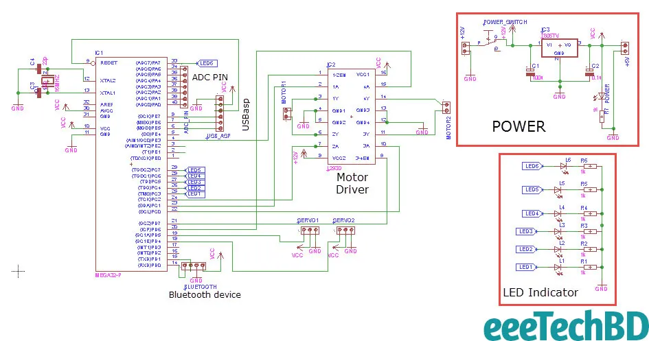
Before Designing the schematic I wanted to make a multi-purpose PCB Board so that I can use the same PCB many other projects like,
- Line Follower Robot
- Bluetooth Interfacing and AVR Serial interfacing
- DC Motor Interfacing with AVR Microcontroller
- servo Interfacing With AVR Microcontroller
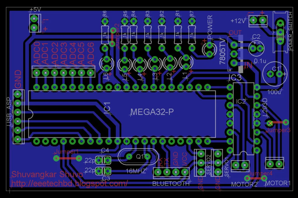
I hope you get the PDF output file(bottom view and top view) of PCB Board design in the zip file you downloaded before.
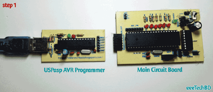
One of my favorite advantages of this PCB board is, I can upload program from computer easily using USBasp AVR Programmer
So brief features of PCB board are
- Small size PCB(3”X2”)
- 2 servo pinout.
- 2 DC motor pinout.
- Bluetooth module HC-05/06 Pinout.
- 7 ADC pinout which you can use for line follower or sensor value reading purpose.
- +5v pinout if necessary to supply extra power .
- +12v power supply pinout.
- USBasp AVR Programmer MOSI, MISO, SCK, RESET, VCC,GND(sequentially) pinout.
- 16Mhz crystal if you need to extend speed of AVR microcontroller.
- 6 Led indicator help you many purposes. If you you use the circuit For the purpose of Line Follower Robot, you can debug 6 IR sensor value.
- You can use 16X2 or 20X4 display connecting 7 adc pins(PA0 to PA6) in the case you don’t use these pin as ADC.
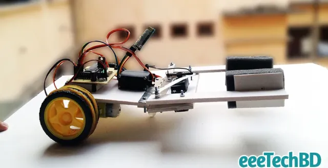
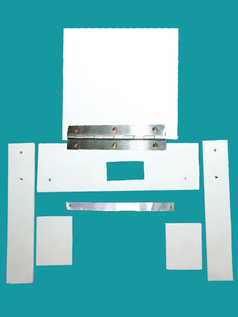
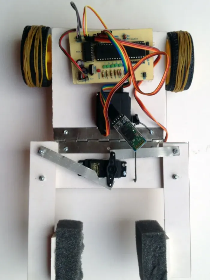
Mechanical Design
I think this is the easiest part. Because you need to make a simple hand and a rectangular shape body. I used plastic wood for body and hand. You can use whatever available to you. I hope Mechanical part will be clear to you after watching two images given below.
Pin Mapping
Before Coding section I give you a list of Pin map So that you can understand which pin of AVR Microcontroller is connected with components like leds, motors, Servos and it will also help you to understand the code easily.
LED
- Led1 -> PC3 (25 No. Pin of Atmega32)
- Led2 -> PC4 (26 No. Pin of Atmega32)
- Led 3 -> PC5 (27 No. Pin of Atmega32)
- Led4 -> PC6 (28 No. Pin of Atmega32)
- Led5 -> PC7 (29 No. Pin of Atmega32)
- Led6 -> PA7 (33 No. Pin of Atmega32)
L293d
- Enable1 -> PB3(4) 8 Bit time 0 OC0
- Enable2 -> PD7(21) 8 Bit timer 2 OC2
- Input1 -> PC1(23)
- Input2 -> PC2(24)
- Input3 -> PC0(22)
- Input4 -> PD6(20)
Servo
- Servo1 -> PD5, 16 Bit Timer1 Channel OC1A
- Servo2 -> PD4, 16 Bit timer1 channel OC1B
Coding
In the point of my view, This is the most interesting part of this project if you have basic knowledge regarding AVR Microcontroller. You have got the Atmel Studio 6 project in the Zip file downloaded before. I hope you understand the code going through for the first time because I commented on majority of the line where you may face problem to understand.
For simplicity of main function I divided the whole coding few parts.
- UART.c and UART.h where I wrote functions for Initializing Serial communication to run bluetooth device HC-05or HC-06.
- Servo_16_BitPWM.c and Servo_16_BitPWM.h where I Wrote For Initializing PWM(Pulse Width Modulation) to Run 2 servo motors.
By the way, I will also make tutorial How I made UART file(UART.c,UART.h), PWM file(Servo_16_BitPWM.c,Servo_16_BitPWM.h) in details.
ANDROID CONTROLLED ROBOT USING AVR MICROCONTROLLER.pdf
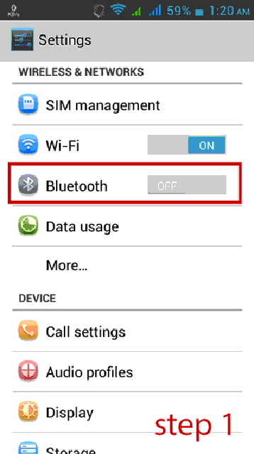
Hex File UploadI hope withing this time you have made circuit and hardware. If you understand the whole code you can customize code. But if you don’t want any hassle then upload the hex file “android car.hex” from zip file you downloaded before using USPasp AVR Programmer.You can use Extreme Burner software for uploading program using USPasp AVR Programmer. Now If you completed everything successfully then this is the time to run your Smart Robot. Pairing Phone with BluetoothBefore opening the Android App you must remember to turn on bluetooth and most important work is to pair the Bluetooth module before connect with Android application I provided before. Here is the simple procedure of pairing the HC-05 or HC-06 Bluetooth module with Android phone
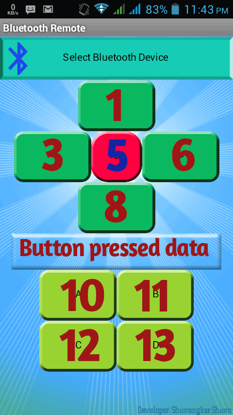
If you watch the video at the beginning of this tutorial, You will understand the remaining process. Obstacle I have faced
- While I prepared the circuit and uploaded the hex file in the Atmega32 the bluetooh was not working. Then I observed that I mistakenly connected Tx pin of Bluettoh device with Tx pin of Atmega32. So Never forget to connect Tx pin of Bluetooh device with Rx pin of Atmega32 and Rx Pin of bluetooh device with Tx pin of atmega32.
- Servo was not working. I initiated PWM of 16 bit timer1 two channel OC1A and OC1B correctly but one big mistake I committed was I did not set PD5(OC1A channel) and PD4(OC1B) in output mode.
- Bluetooth was connected perfectly but after sending first command The Application hanged and no button was working and connection lost.Finally I understood Android mobile application sending data continuously but the Microcontroller serial Buffer(FIFO buffer) can not receiving data simultaneously as well as buffer can not make room for the upcoming byte. As a result the connection lost and application hang. So what I did in the coding section, I simply flushed the UART Serial buffer after receiving one byte of data and problem solved :D.
- Sometimes I observed that the bluetooh device was not connecting and android Application gave me the error message “Error 507, unable to connect…” . I restarted the Circuit and Mobile So problem solved. You can use another bluetooth application available at Playstore. Though it’s User Interface was not satisfactory but it was working smoothly while my application was gave me error messages few times. You just have to set the same data that I send from my application given below
Please feel free to let me know what types of problems you face
Improvements
- More facilities can be added to the android application Like Auto connect, button value change, Disconnect button etc.
- Motor speed can be controlled using PWM
- AVR Microcontroller operation speed can be increased up to 16 Mhz changing Fuse bit
- This Robot can be converted into Automatic Goods Finder and carrier Robot
👋 About Me
Hi, I’m Shuvangkar Das — a power systems researcher with a Ph.D. in Electrical Engineering, currently working as a Research Engineer at EPRI. I work at the intersection of power electronics, inverter-based DERs (IBRs), and AI to help build smarter, greener, and more stable electric grids.
My work spans large-scale EMT simulations, firmware development, reinforcement learning, and hardware prototyping. Beyond engineering, I’m also a YouTuber and content creator — sharing hands-on insights on productivity, research, and knowledge management. My goal is simple: to make complex ideas more accessible and actionable for everyone.
Real stories. Practical lessons. Right in your inbox.
No spam—just once a week.
Connect with me:
Leave a comment