
Automatic Water Pump Controller Using Bjt
This is one of my favorite analog electronics projects because this is the lowest cost but efficient automatic water pump controller. Components require for this project are
- 3 BJT model BC547,
- 1 Buzzer,
- 1 Relay,
- 8 Resistors,
- 1 Diode,
- 1 Led,
- Wires for sensing water level.
So all the components cost not more than $1.
I hope all of you guys have fun with this low cost exciting project. I will explain design procedure of every parts so that you can use BJT switch any of your project. Before we start let’s see the project demo video.
Buzzer Part design:
Buzzer is used for indicating whether there is water in the water tank or not. If there is no water in the water tank buzzer will turn on. So I have to put two terminals of the wire at the bottom of the water tank.
- Buzzer current requirement: 35mA maximum
- Voltage: 3.5-5V
- buzzer coil resistance: 42R
- Buzzer will be turn on when there is no water in the water tank and turn off when water level start rising.
So now one thing is clear we have to design transistor such a way so that it works in cut-of region and saturation region as well as supply 30mA(close to 35mA) current. If you don’t know much about BJT switching, it is suggested to go through this tutorial TRANSISTOR AS A SWITCH : DESIGN PROCEDURE.
The image given below is our final design. You see, it is supplying 33mA current through the buzzer.
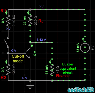
Circuit parameters:
\[V_{CC} = 9V\] \[R_{buzzer} = 42\Omega\] \[I_{buzzer} = 30mA\]Collector resistance calculation:
\[I_{buzzer} = \frac{V_{CC}}{R_C + R_{buzzer}}\] \[R_C = 258\Omega\]Nearest available value is 230 ohm.
For calculating R1 & R2 values we need the Thevenin equivalent of above circuit.
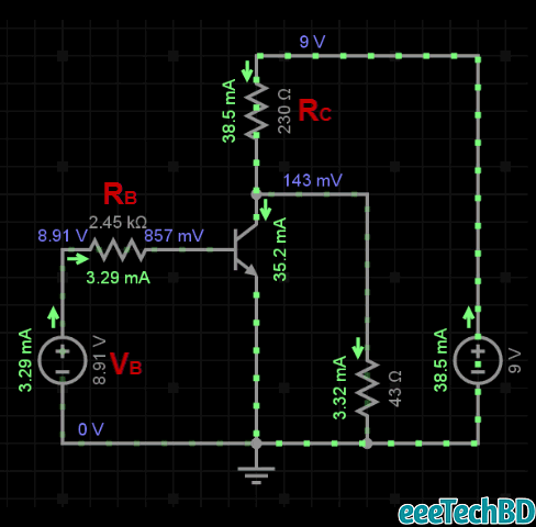
Thevenin voltage and resistance are:
\[V_B = \frac{R_2}{R_1 + R_2}\] \[R_B = \frac{R_1 R_2}{R_1 + R_2}\]Now we calculate collector and base current:
\[I_{C|EOS} = \frac{V_{CC} - V_{CE|Saturation}}{R_C}\] \[I_{C|EOS} = \frac{9 - 0.2}{220} = 40mA\] \[I_{B|EOS} = \frac{I_{C|EOS}}{\beta_{min}}\] \[I_{B|EOS} = \frac{40mA}{110} = 0.3636mA\]Overdrive factor ODF = 10.
\[I_B = ODF \times I_{B|EOS}\] \[I_B = 10 \times 0.3636mA = 3.636mA\]N.B: If Thevenin voltage VB very close to power supply voltage Vcc=9v then the transistor will operate deep into saturation
Let assume VB = 99% of Vcc
\[V_B = 8.91V\] \[I_B = \frac{V_B}{R_B}\] \[R_B = \frac{V_B}{I_B}\] \[R_B = \frac{8.91V}{3.636mA} = 2450\Omega\]Now we find out values for R1 & R2.
As VB very close to Vcc, so the R2 value should be enough greater than R1 value. let R2 = 100k
\[R_2 = 100k\Omega\] \[R_B = \frac{R_1 R_2}{R_1 + R_2}\] \[2450 = \frac{R_1 \times 100k}{R_1 + 100k}\] \[R_1 + 100k = \frac{R_1 \times 100k}{2450}\] \[R_1 + 100k = 40.8 R_1\] \[R_1 = 2512.56\Omega\] \[R_1 \approx 2.5k\Omega\]Our calculated values are close to simulation value.
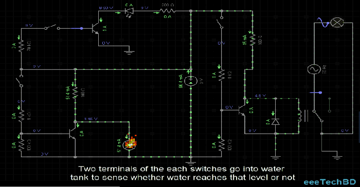
So when the water level doesn’t reach that height current cannot pass through Base(Base grounded). So BJT operates in the Cut-off region.
Relay part design:
Two terminals of the wire will put at the top of the water tank. So when water tries to overflow, the motor automatically turns off.
As electronics circuit part is operating in 9v. But we need to turn on and off the Ac water pump. So we need a relay to operate the water pump. But relay requires much current close to 70mA.
I used relay model SRD-05VDC-SL-C
Relay current requirements: 70 mA
voltage: 5V
As calculations are same as Buzzer part, you can calculate necessary resistors value to operate relay if you understand Buzzer part design. Here only change is Collector current Ic
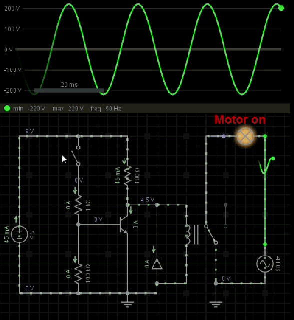
Here Diode parallel with Relay is used keeping the BJT safe from high voltage generated by relay which may break downs the BJT. So when high voltage generates across relay coil, it pass through diode to the battery.
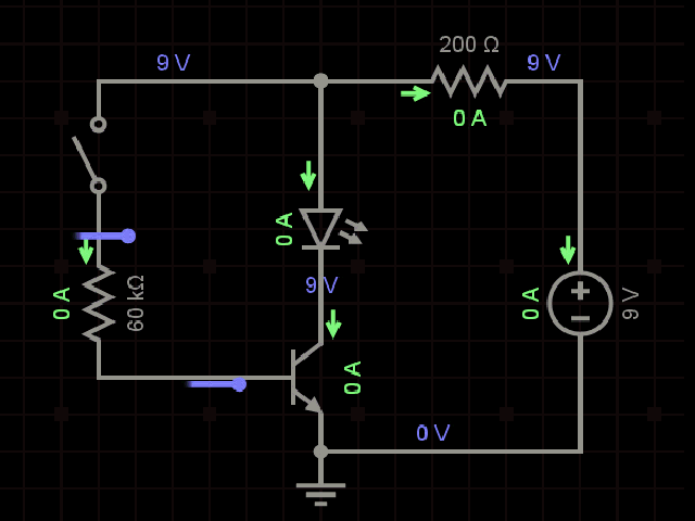
Led Part design:
Led is optional part. When water is middle of the water tank led will turn on. So I have to put two terminals of the wire at the middle of the water tank.
I used 3mm Led which requires 10mA current.
To minimize BJT power consumption, design the transistor in saturation mode.
Follow this tutorial to design this part.
For better view of the full schematic go This link
Point to remember:
After completing design choose BJT model according to your current rating(maximum allowable current through collector) and power rating. So check my model BC547. Collector current(DC) of BC547 is 100mA and our Relay requires 70mA. We can use this model. If you want to be more safe, use PN2222 which collector current is 600mA
Leave a comment