
Multiplexing Serial Port For Arduino And Microcontroller Project
A few years back I developed a project SIM module-based IoT data logging system for sensor data. The project was based on ATmega328P which is the heart of Arduino Uno. I used SIM800L for internet connectivity and RS480 bus used for communicating with the sensor nodes. In the project, I needed 3 serial ports. The first hardware serial port for debugging purposes and the second serial port for the SIM800L module and the third serial port for RS485 communication. A single serial port consumes an average of 256 bytes of RAM just for the buffer. Therefore, a total of 768 bytes of RAM are needed for all the 3 serial ports which are 36% of the RAM ATmega328 has.
Optimizing RAM is one of the crucial factors of microcontroller programming. In the case of serial communication, you cannot connect more than one device to a particular serial port. The TX pin will work sometimes but not RX. Then, I came across the idea of multiplex a serial port between SIM800L and RS485. In that case, I can debug my system with one hardware serial and connect SIM800L and RS485 to another software serial. That saves me another serial port.
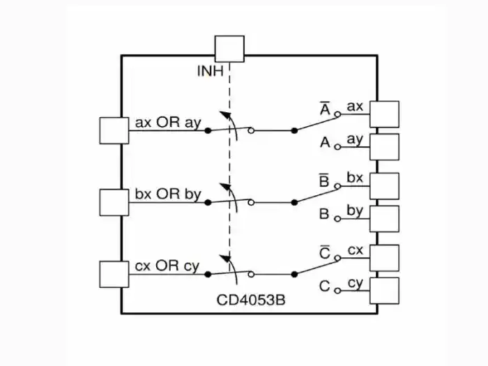
I used a digital logic IC model 4053(CD4053, 74HC4053) for multiplexing the serial port. It is a triple 2 channel analog multiplexer/demultiplexer IC. A few features of the IC that are useful for the projects are:
- IC works exactly like an analog switch. Therefore, It can achieve bidirectional communication.
- Wide digital input voltage range. Digital 3-15V and analog 12Vp-p
- Low on-resistance 80Ohm typically and high off resistance
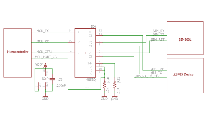
 For communicating with the SIM800L module you need 3 pins. RX, TX, and another reset. Similarly, for communication with the RS485, you need 3 pins. RX, TX, and another pin for controlling whether the IC will work as TX mode or RX mode. For both of the devices, you need to multiplex three pins. Therefore, 2 triple channel analog multiplexers are a perfect fit for such type of application. The figure below demonstrates the simplified schematic of such a setup.
 For selecting a channel, here is the pin mapping:
 - A,B,C, INH pins are low, X, Y, Z are connected with X0, Y0, Z0
- A,B,C pins are high and INH is low, X, Y, Z are connected with X1, Y1, Z1 This is not a difficult choice, right? Happy tinkering!!
Shuvangkar Das, Dhaka, Bangladesh
Leave a comment