
Use Checksum Intelligently For Finding Communication Error In Embedded Project, Part 1
 As an embedded system engineer, I used to deal with lower level communication protocol such as UART, SPI and I2C. I used to trust SPI protocol rather than other protocols. This trust killed my two weeks at the middle of 2020 while working on an IoT sensor node project. Today, I will tell you the story of my weirdest struggle with hardware communication protocols.
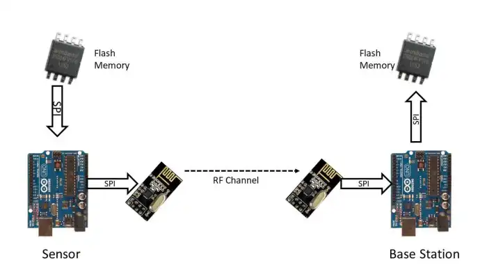
At that time, I was working on a IoT sensor node project. The system had a base station and hundred of sensor nodes. The sensor nodes store data in flash memory and after a certain interval, it sends data to the base station. By this way, we reduced communication burden. The Base station stores that data upon receiving. Then it sends the data to the server after processing. In the whole path, there are multiple layers of communications.
- Sensor node read sensor data in one second interval and store in a flash memory using SPI protocol.
- Sensor node read data from flash memory after 1 minutes and makes a packet and sends to the base station using nRF24L01 RF module. This has SPI and RF communications
- The base station reads sensor node data packet using SPI and store in flash memory in SPI protocol.
The figure at the beginning demonstrates the communication scenarios.
In the whole data path, there are 4 layers of SPI communication and one layer of RF communication. The nRF24L01 module uses CRC in its RF communication protocol, therefore you can consider that there is no error in nRF24L01 communication. If do, I cannot see the data at the base station.
So one day, while I was checking data at the base station, I found lot of garbage data coming from the sensor node. I checked all four layers of SPI communication protocol in the whole path from sensor node to the base station. I could not figure out which communication layer injecting noise into the data. After one week I got frustrated. Later, I and Shakil, one of my fellow junior engineers figured out that the main culprit was the base station PCB. The base station PCB has problem in its SPI lines, so it was injecting garbage data. Data is ok up to Base station radio. While the base station MCU reading data from the radio, the data was getting into garbage due to the SPI PCB tracing.
At that time, I lost all trust on communication protocols and there should be a mechanism so that data mismatch can be found easily in any layer. For that, you need variable that holds the data signature, so that you can check the signature in each layer of the communication protocol. For this reason, all standard communication protocols use checksum, CRC and hash function. Later, I used checksum with all the packets to find out such data mismatch.
What is checksum?
Consider, you have the following data packet, data[] = [20, 67, 80, 45, 140]. You need to send this data to another device. There is a chance of data being corrupted due to noise in the communication protocol or design flaw. So, can you detect this data corruption?
You give some a cheque. So, how did back verify that the cheque is issued by you? The bank has your signature sample. So they will use your cheque signature with their sample. If I apply the same analog with our data packet. I will attach a signature with my data packet. So when receiver will receive the data it will calculate the signature and match with your attached signature. By this way, the receiver device can identify that data is valid or not.
Now the question might come up, how do you calculate signature of the packet? There are many ways to calculate signature. The simple one that a microcontroller can handle is checksum. CRC is another option. But is computationally than checksum.
To calculate checksum:
- add all the bytes in the packet and keep the sum in 16 bit integer
- Keep only the lowest 8 bits from the 16 bits sum.
Let’s calculate the checksum for data packet. data[] = [20, 67, 80, 45, 140] 20+67+80+45+140=352 = 0b0000 0001 0110 0000 Keeping the only the lowest 8bits 0b0110 0000 =96. So, 96 is our checksum signature of data packet. Now add the checksum at the end of the packet. data[] = [20, 67, 80, 45, 140, 96] So easy to calculate !right?
How to use this technique for detecting data error
The idea of checksum is very simple yet powerful. When you measure your sensor data, you created a packet with checksum and store the packet in flash memory. Next time, you want to send to the packet to server, first you read the packet and calculate checksum to verify data integrity. You will do this step in every step of communication. By this way, you can identify easily which layer is corrupting your data packet.
That’s all for today. In the next blog, I will explain the checksum with source code in Arduino and don’t forget the rule of working with communication protocol.
“Never trust the bitch”
Shuvangkar Das, Dhaka, Bangladesh
Leave a comment